How to Install the Baker Infield UV Light Kit for Your Biosafety Cabinet
Here is our comprehensive guide on installing the Baker Infield UV Light Kit in your biosafety cabinet. This blog post is designed to assist users who often ask, “How do I install the Baker Infield UV Light Kit?” or express concerns such as “I’m having trouble installing the UV light kit.” We will provide detailed, step-by-step instructions to help you complete the installation process efficiently and safely.
Tools Needed
Before you begin, ensure you have the following tools:
- Hex wrench (depending on your cabinet model)
- Philips head screwdriver
- Small flat head tool to insert wires into terminal block
- Safety gloves
- UV light kit components (UV bulb, UV ballast, tombstones and plates, warning label, required hardware, wire ties)
Step-by-Step Guide to Installing the UV Light Kit
Step 1: Power Down the Cabinet
Details:
- First, unplug the biosafety cabinet and ensure that it is completely powered down, avoiding any electrical hazards.
Step 2: Remove the Dress Panel
Details:
- Unscrew the screws securing the dress panel, located on the bottom left and right of the panel. Depending on your cabinet model, the screws securing the dress panel may require a hex wrench or can be thumb screws.
- Grasp the dress panel in the center and raise it. Once raised, support the panel using the support arm kickstands on the right and left-hand sides to secure it in place.
Step 3: Install the UV Ballast
Details:
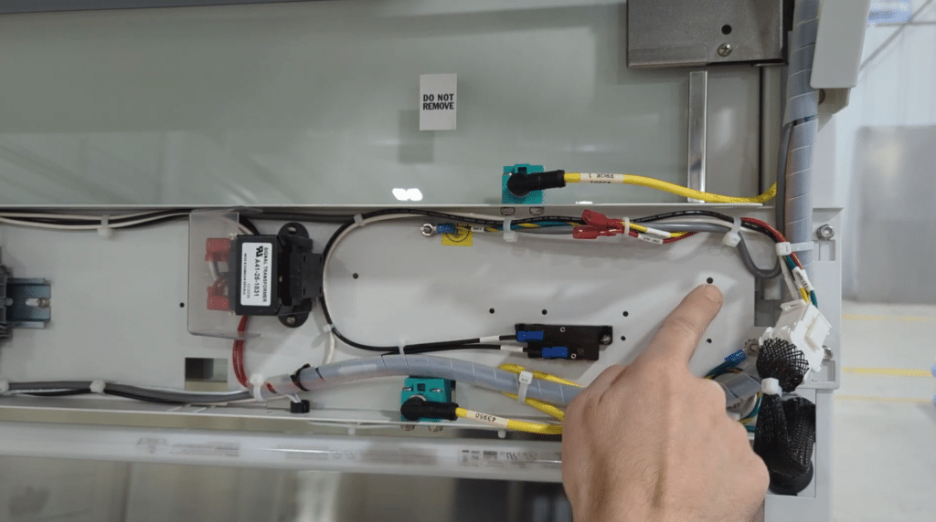
- Locate the mounting position for the UV ballast, typically to the right of the transformer and above the circuit breaker.
- Use the provided hex screws and washers to mount the ballast. Pre-installing the screws can be helpful for thread cutting.
- Once the ballast is in place, tighten the hex screws.
Step 4: Wire the UV Ballast
Wiring the ballast will require wiring the input side and output side. The factory capped wires are to remain capped and will not be used. Wire the output side first.
Details:
- Output Side: Connect the red and yellow output wires from the ballast to the corresponding wires on the cabinet.
- Input Side:
- At the solid-state relay, remove the blank terminals from B1 and B2.
- Connect the loose black wire to B1 and the black wire from the ballast to B2.
- At the terminal block, terminals 1 through 3 are all AC hot and jumpered together. Terminals 4 through 6 are all AC neutral and jumpered together.
- Next, connect the black wire from B1 on the relay to any open AC hot terminal, and the white wire from the ballast to any open AC neutral terminal.
- To connect the wire, insert a small flat head into the square hole to open the terminal, once the wire is inserted into the round hole remove the flat head from the square hole to close the terminal onto the wire.
Step 5: Secure the Wires
Details:
- At this point the wiring of the ballast is complete.
- Use the provided wire ties to secure all wires in an orderly manner, ensuring they are neat and out of the way.
Step 6: Install the Tombstone Plates
Details:
- Locate the UV tombstone blanks on the back wall of the cabinet, below the supply filter diffuser.
- Carefully unscrew the plates, exposing the connected tombstone wires.
- Locate the new tombstones and install them into the newly provided plates.
- One tombstone can accommodate one wire, the other takes two wires, install these on the corresponding sides matching the number of wires needed accordingly by pushing the wire(s) into the square hole(s) on the back of the tombstones.
- Re-install the tombstones using the screws previously holding the blank plates.
Step 7: Install the UV Bulb
Details:
- Insert the UV bulb into the tombstones.
- One tombstone will have a plunger, that is the side to insert first and then the other side will should fit into place.
- Take care that the UV bulb is cleaned of any grease from direct contact with skin to ensure longest life, and use gloves when installing to ensure the bulb stays clean.
Step 8: Reassemble the Cabinet
Details:
- Lower the dress panel and secure it with screws on both sides.
- Reconnect the cabinet power and restart your cabinet.
Step 9: Test the UV Light
Details:
- The UV bulb will only operate when the sash is closed. If the user attempts to turn on the UV light with the sash open, an alarm light will blink once to notify you that the sash must be closed.
- Once the sash is closed the fluorescent light will shut off.
- You can now turn on the UV light. When the sash is raised, the UV light will automatically turn off.
By following these steps, you can successfully install the Baker Infield UV Light Kit in your biosafety cabinet. This guide ensures your laboratory maintains a safe environment, essential for various microbiological and pharmaceutical procedures.
Troubleshooting Common Issues
If you encounter any issues during installation, double-check the wiring connections and ensure the power is properly disconnected and reconnected as instructed. Refer to the manufacturer’s guidelines for additional support or contact Baker Company for assistance.
Watch the Step by Step video!